
Views: 0 Author: Site Editor Publish Time: 2026-09-11 Origin: Site


Unmonitored static electricity poses severe, quantifiable risks in industrial and research environments. From electrostatic discharge (ESD) instantly destroying sensitive semiconductor components to severe material jamming in high-speed web converting, invisible surface charges cause critical latent defects and production halts. The core technical challenge lies in measuring this surface voltage without physically contacting the material. Physical contact alters the existing charge, drains the potential, or triggers a destructive discharge event. To solve this, engineers rely on the electrostatic sensor as the standard non-contact diagnostic tool. This guide provides a technical evaluation of sensor mechanics, differentiating between field meters and voltmeters. You will learn how to select the correct instrumentation based on spatial resolution, environmental vulnerabilities, and specific operational environments to protect product yield and maintain process stability.
Non-Contact Necessity: Electrostatic sensors utilize capacitive coupling and electrostatic induction to measure surface charge without physical contact, preserving the integrity of the measured surface.
Technology Bifurcation: The choice of instrumentation typically splits between Electrostatic Field Meters (best for general static audits and broad areas) and Electrostatic Voltmeters (required for high-precision, distance-independent surface potential measurement).
Environmental Vulnerability: Sensor accuracy is highly dependent on strict grounding protocols, controlled measurement distances, and mitigation of environmental factors like humidity and electromagnetic interference (EMI).
Application-Driven Selection: Procurement decisions must prioritize spatial resolution, response time, structural parameters, and integration capabilities (inline vs. handheld) over baseline cost to ensure reliable yield protection.
Table of Contents
Accurate surface voltage measurement requires detecting static fields without draining the charge you intend to measure. Any physical probe touching a charged dielectric or isolated conductor acts as a grounding path. This immediately alters the electrical state of the target. Non-contact measurement solves this by reading the electric field emitted by the surface charge across an air gap. Engineers must understand the underlying physics to deploy these instruments effectively across different manufacturing environments.
The fundamental operating principle relies on the electrostatic induction model. When a charged surface exists, it projects an electric field outward. Placing a conductive probe within this field causes the free electrons in the probe to redistribute. A positively charged target pulls electrons toward the face of the probe, while a negatively charged target pushes them away. This redistribution induces a proportional electrical signal within the internal circuitry of the device.
The mathematical relationship governing this interaction links charge density, electric field strength, and distance. The electric field strength is directly proportional to the surface charge density and inversely proportional to the square of the distance from the source. Capacitive coupling occurs between the target surface and the sensing electrode. The air gap acts as the dielectric medium. As the distance increases, the capacitance decreases, which inherently weakens the induced signal unless the instrument actively compensates for the spatial gap.
Physical Variable | Impact on Measurement Signal | Engineering Compensation Strategy |
|---|---|---|
Air Gap Distance | Signal strength drops exponentially as distance increases. | Utilize closed-loop feedback mechanisms or strict mechanical mounting brackets. |
Surface Charge Density | Directly dictates the intensity of the projected electric field. | Adjust internal amplifier gain settings based on expected voltage ranges. |
Dielectric Constant of Air | Fluctuates slightly with extreme humidity, altering capacitance. | Implement environmental controls or algorithmic humidity compensation. |
Physical design directly dictates measurement sensitivity and spatial resolution. The probe aperture size determines the field of view. A wide aperture captures a broad area of the electric field, providing an average reading of a large surface. This design increases overall sensitivity but sacrifices spatial resolution. You use wide apertures when monitoring large plastic webs or wide conveyor belts where localized pinpoint accuracy matters less than the overall static trend.
Conversely, a narrow aperture restricts the field of view. This allows the instrument to pinpoint localized charge pools on a small component, such as an individual microchip on a printed circuit board. Restricting the aperture reduces the amount of induced current. Engineers must balance electrode geometry against the required measurement precision. Heavy metallic shielding around the sensing electrode prevents stray fields from adjacent charged objects from interfering with the primary measurement path.
Every electrostatic sensor requires a definitive reference point to provide accurate readings. This reference point is earth ground. The instrument measures the potential difference between the charged surface and this known zero-volt baseline. Without a verified ground, the data output is entirely meaningless.
Internal circuitry translates the minute induced current into a readable voltage metric. High-impedance electrometers amplify the induced charge. Without a solid ground connection, the instrument itself floats electrically. A floating instrument accumulates its own static charge from handling, air flow, or environmental friction. This internal charge offsets the baseline, resulting in wildly inaccurate readings. Proper grounding ensures the internal reference remains at absolute zero, allowing the circuitry to isolate and amplify only the signal induced by the target surface.
The industry divides non-contact static measurement into two distinct operational paradigms. Selecting the correct solution category depends entirely on the required precision, the target material, and the physical constraints of the measurement environment. Deploying the wrong technology guarantees false data and subsequent yield losses.
Static electric fields are direct current (DC) phenomena. Standard electronic amplifiers struggle to measure DC fields accurately over time due to baseline drift. Electrostatic field meters solve this using a mechanical "chopper" mechanism. A grounded, vibrating metallic vane rapidly covers and uncovers the sensing electrode. This mechanical oscillation chops the continuous DC electric field, converting it into an alternating current (AC) signal.
The internal circuitry easily amplifies this AC signal without suffering from DC drift. Once amplified, the system demodulates the signal back into a DC voltage reading for the display. This mechanical conversion is highly reliable but requires specific maintenance protocols to ensure longevity in harsh industrial environments.
Broad-area static audits across expansive factory floors.
Identifying general static build-up locations on packaging lines.
Monitoring moving webs in paper, textile, or plastic film manufacturing.
Triggering overhead ionization blowers when bulk charge exceeds safety thresholds.
Field meters are highly dependent on a fixed distance from the target. The factory calibrates them for a specific gap, typically one inch. Moving the meter closer or further away drastically skews the reading. They also offer lower spatial resolution, averaging the charge over a wide area. If a highly charged spot sits next to a grounded metal fixture, the field meter will average the two, masking the dangerous peak voltage.
Electrostatic voltmeters utilize a sophisticated closed-loop feedback mechanism to eliminate distance dependency. Instead of simply reading the induced charge, the voltmeter actively drives the potential of its own probe housing to match the potential of the measured surface. This active driving mechanism represents a significant leap in measurement technology.
When the probe detects an electric field, a high-voltage amplifier energizes the probe body. The amplifier continuously adjusts this voltage until the electric field between the probe and the target surface reaches zero. At this null point, the voltage applied to the probe exactly equals the unknown surface voltage. The instrument then displays the amplifier's output voltage.
High-precision research and development laboratories.
Semiconductor wafer manufacturing and handling stations.
Measuring specific points on complex dielectric materials.
Analyzing charge decay rates on specialized insulative coatings.
Measurement accuracy remains largely independent of the probe-to-surface distance. As long as the target fills the probe's optical aperture, the reading remains stable. This technology also provides exceptionally high spatial resolution for pinpoint diagnostics. The primary trade-off involves the physical size of the high-voltage amplifier and the complexity of the feedback circuitry.

Feature | Electrostatic Field Meter | Electrostatic Voltmeter |
|---|---|---|
Primary Mechanism | Chopper-stabilized (DC to AC conversion) | Closed-loop feedback (Null-seeking) |
Distance Dependency | High (Requires fixed measurement gap) | Low (Independent within operational range) |
Spatial Resolution | Low (Averages broad areas) | High (Pinpoint measurement capability) |
Maintenance Needs | Mechanical chopper wear, regular cleaning | High-voltage amplifier calibration |
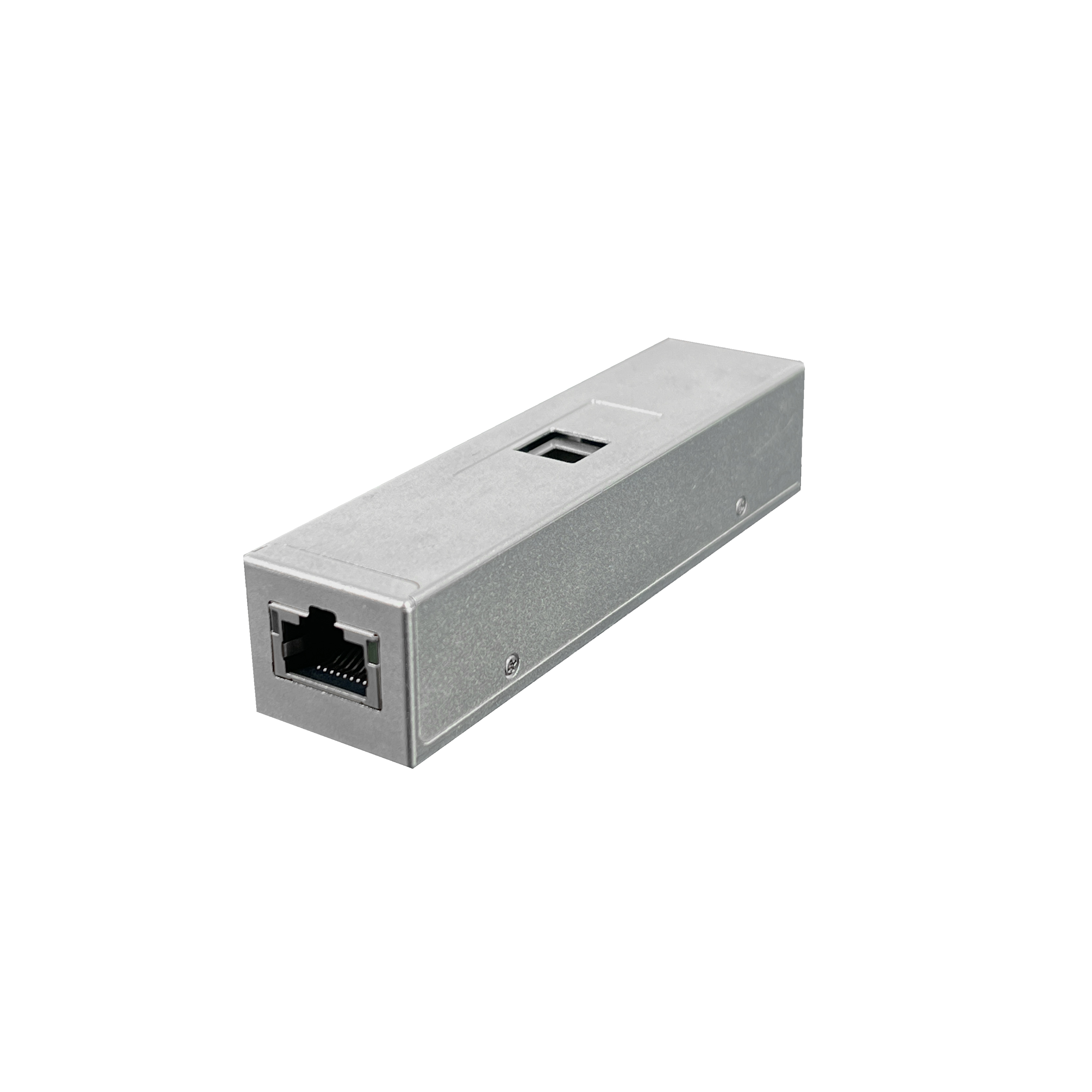
Selecting the appropriate instrumentation requires mapping technical specifications to real-world operational constraints. A rigorous evaluation framework ensures the chosen device performs reliably under specific facility conditions. You must analyze the physical layout of your machinery and the electrical properties of your materials before finalizing any hardware specifications.
The distance between the sensing head and the target heavily dictates the effective spot size. Think of the sensor's field of view as an expanding cone. The further you pull the device away, the wider the cone becomes. A wide cone averages the charge across a large surface area. You must calculate the exact spot size based on the manufacturer's specified viewing angle to ensure you are not inadvertently measuring background grounded metal.
Proximity increases spatial resolution and accuracy. Moving the probe closer shrinks the spot size, allowing you to isolate specific components. Extreme proximity introduces the risk of arcing. In high-voltage environments, placing a grounded probe too close to a highly charged surface will cause the static electricity to jump the air gap. This discharge damages the material and potentially destroys the sensor circuitry. Engineers must calculate the safe standoff distance based on the maximum expected voltage and the dielectric breakdown strength of air, which is approximately 3kV per millimeter.
Monitoring high-speed manufacturing processes requires rapid response times. In roll-to-roll printing, plastic film extrusion, or automated packaging, the material moves past the measurement point at hundreds of feet per minute. A slow instrument will miss rapid fluctuations in surface charge, displaying an artificially smoothed average that hides dangerous voltage spikes.
Bandwidth dictates how quickly the internal circuitry reacts to a changing electric field. Static objects require minimal bandwidth. You can hold a meter over a stationary plastic tote and wait a full second for the reading to stabilize. Monitoring a rapidly fluctuating charge environment demands high bandwidth. Inline process monitoring systems often require response times in the low milliseconds to trigger active ionization equipment accurately. If the sensor lags, the ionizer will deploy neutralizing charges too late, missing the charged section of the web entirely.
Material properties fundamentally alter charge distribution. Conductive materials allow electrons to flow freely. If an isolated conductor holds a static charge, that charge distributes evenly across its entire surface. Measuring one point on a conductor provides the voltage for the entire object. You can place the sensor anywhere on the conductive body and receive an accurate representation of its total potential.
Dielectrics, or insulators, behave differently. They restrict electron flow. A plastic sheet can hold a massive positive charge in the center while remaining completely neutral at the edges. Measuring dielectrics requires scanning the entire surface to locate localized charge pools. Calibration adjustments become necessary when measuring insulators because the electric field lines do not project uniformly. Field meters often require specific grounded backing plates behind thin dielectric films to force the electric field lines straight toward the sensing head, preventing field distortion.
Human operators generate significant static charges simply by walking across a floor or shifting in a chair. This human-induced ESD poses a massive threat in electronics assembly. Measuring operator charge requires specialized techniques because the human body acts as a large, mobile conductor with varying capacitance depending on footwear and flooring.
Wireless human body voltage measurement utilizes a specific methodology. You cannot easily attach a wired probe to a moving operator without restricting their workflow. Instead, the electrostatic sensor points at a conductive plate. The operator touches or stands near a system that brings this plate to approximately the same potential as the user. The instrument then measures the voltage of the stationary plate, indirectly monitoring the human body voltage. This setup allows facility managers to verify the effectiveness of ESD flooring and heel straps in real-time.
Even the most advanced instrumentation fails if deployed without mitigating environmental variables. Real-world industrial settings introduce severe challenges that skew readings and degrade sensor performance. You must engineer your measurement stations to account for ambient conditions and electrical noise.
Ambient moisture acts as a natural static dissipator. High humidity levels create a microscopic, invisible layer of conductive water on surfaces. This moisture bleeds off static charges quickly. While high humidity reduces ESD risks, it also masks the true static generation rate of a process. If you measure a process during a humid summer month, you might falsely conclude the process is safe, only to experience massive yield losses during dry winter months.
Temperature fluctuations alter the physical dimensions of the measurement gap and the internal components of the sensor. Extreme heat causes thermal drift in high-impedance amplifiers. Facilities must maintain controlled environments or utilize sensors with built-in temperature and humidity compensation algorithms to ensure baseline stability. Mounting sensors near industrial ovens or cryogenic cooling lines requires specialized thermal shielding to protect the electrometer circuitry.
Poor facility grounding destroys measurement accuracy. If the earth ground connection degrades due to corrosion or loose wiring, the instrument loses its zero-volt reference. The readings will float randomly, rendering the data useless. Ground loops, where multiple ground points sit at slightly different potentials, introduce severe noise into the measurement signal. You must tie all measurement equipment to a single, verified facility ground bus.
Natural sensor drift occurs over time. Electronic components age, and mechanical choppers wear down. Routine calibration schedules combat this drift. Industrial protocols mandate annual or bi-annual calibration using NIST-traceable high-voltage power supplies and precision micrometers to verify distance accuracy. Operating uncalibrated sensors creates a false sense of security, leading engineers to ignore actual static threats.
High-impedance circuitry is inherently susceptible to electromagnetic interference (EMI) and radio frequency interference (RFI). Industrial environments are saturated with electrical noise from heavy machinery, variable frequency drives (VFDs), and wireless communication networks. This ambient noise induces false currents in the sensor probe, causing erratic voltage spikes on the display.
To mitigate this, engineers must deploy strict shielding strategies across the entire measurement loop.
Use heavy braided shielding on all sensor cables, tying the shield to ground at one end only to prevent ground loops.
Route measurement cables in dedicated grounded conduits, far away from high-voltage power lines or motor leads.
Implement signal conditioning strategies, such as low-pass filters, to strip out high-frequency industrial noise before it reaches the data acquisition system.
Enclose the sensor head in a grounded Faraday cage if measuring in highly volatile RF environments, leaving only the optical aperture exposed to the target.
Procurement and engineering teams must align instrument capabilities with the specific demands of the production floor. The selection process requires a clear decision matrix prioritizing integration needs, hardware reliability, and data output formats. You must evaluate how the sensor will communicate with your existing factory automation infrastructure.
Permanent, inline sensors provide continuous oversight. These units mount directly onto machine frames, monitoring web lines or conveyor belts in real-time. They integrate seamlessly with Programmable Logic Controllers (PLCs) via standard 4-20mA or 0-10V analog outputs. This integration enables automated responses, such as triggering ionization bars or halting production if surface voltage exceeds safe thresholds. Real-time visualization via PC software and continuous data logging capabilities are mandatory for inline systems to track historical trends and prove compliance during quality audits.
Handheld diagnostics serve a different purpose. Portable, battery-operated units allow engineers to perform spot-checks, audit workstations, and troubleshoot specific machinery. While they lack continuous data logging, their mobility makes them indispensable for daily facility management. A robust static control program requires both inline monitoring for critical processes and handheld units for general auditing. Handheld units must feature ruggedized housings to survive drops on concrete factory floors.
The market has seen a proliferation of low-cost, DIY static detectors, often based on open-source microcontrollers. These devices work well for basic prototyping or educational demonstrations. They lack the rigorous engineering required for industrial use and will fail under continuous operational stress.
Consumer-grade components lack heavy EMI shielding, making them useless near industrial motors. They suffer from severe thermal drift and do not hold NIST-compliant calibration. Deploying uncalibrated, unshielded sensors in a critical yield environment guarantees false readings. Industrial-grade instruments feature precision-machined apertures, hermetically sealed electrometer circuits, and traceable calibration certificates. Yield protection demands industrial-grade reliability. You must verify the manufacturer's specifications regarding mean time between failures (MTBF) and environmental operating limits before authorizing procurement.
The selection of non-contact static measurement equipment dictates your ability to protect sensitive components and maintain process speeds. The choice fundamentally splits between the precise, distance-independent capabilities of an electrostatic voltmeter and the broad, general monitoring strength of a field meter. You must engineer the installation to account for ambient humidity, EMI, and strict grounding protocols to ensure data integrity.
Take the following actions to secure your production environment:
Map out all high-risk static generation points across your facility floor to determine the required number of measurement nodes.
Measure the physical standoff distances available at each critical monitoring location to calculate the resulting spot size.
Consult with an applications engineer to match sensor bandwidth to your specific line speeds and material types.
Request technical datasheets to verify EMI shielding capabilities and calibration traceability for your quality management system.
A: A field meter measures the electric field using a mechanical chopper to convert DC to AC, requiring a strict, fixed distance to the target. A voltmeter uses closed-loop feedback to drive its probe to the same potential as the surface, providing high precision independent of the measurement distance.
A: Yes. These instruments are specifically designed to measure charge on non-conductive surfaces without making physical contact. Because dielectrics hold localized charge pools, you must scan the surface to find peak voltages rather than measuring a single point.
A: For field meters, changing the distance directly alters the reading; they must remain at their calibrated gap. For voltmeters, distance does not significantly affect accuracy as long as the target fully covers the probe's optical field of view.
A: Yes. Instead of wiring a probe to a moving person, the sensor points at a stationary conductive plate. The human operator stays in close proximity or touches a contact point linked to the plate, allowing the sensor to read the plate's voltage, which mirrors the operator's potential.
A: The size of the probe aperture determines the field of view. A larger aperture captures more electric field lines, increasing overall sensitivity but lowering spatial resolution. A smaller aperture provides pinpoint resolution for small components but captures less signal.
A: Industrial environments typically require annual calibration. However, instruments deployed in harsh conditions with extreme temperature fluctuations or high physical vibration may require bi-annual calibration to correct mechanical wear on choppers and thermal drift in electronic components.
A: The sensor measures the potential difference between the charged surface and earth ground. If the instrument is not properly grounded, its internal circuitry floats electrically. It will accumulate its own static charge, shifting the baseline and producing completely inaccurate measurements.
