
Views: 0 Author: Site Editor Publish Time: 2026-09-11 Origin: Site


Static charge represents an invisible threat in semiconductor fabrication, medical device assembly, and advanced electronics production. Unverified ionization equipment gives a false sense of security on the factory floor. Industrial ionizers degrade over time due to inevitable emitter pin wear and environmental contamination. Without rigorous verification, an unbalanced ionizer actively charges isolated conductors and process-required insulators. This unintended charging causes catastrophic yield loss, latent electrical overstress (EOS), and electrostatic discharge (ESD) defects that compromise product reliability.
Standardized performance verification is a fundamental requirement for quality control. Relying on assumptions about equipment functionality exposes manufacturing lines to severe risk. This guide details the technical procedures, equipment requirements, and industry-standard frameworks required to execute a compliant ion balance test and decay time evaluation. Implementing these protocols ensures your static control infrastructure performs exactly as engineered.
Testing Location is Critical: Performance must be measured at the actual work surface where static-sensitive components reside, not directly at the ionizer's emitter points.
Standardized Metrics: A compliant ion balance test (measuring offset voltage) and decay time test (neutralization efficiency) must align with industry standards like ANSI/ESD STM3.1.
Equipment Precision: While handheld field meters offer quick checks, critical environments require a calibrated Charged Plate Monitor (CPM) for accurate, verifiable data.
Continuous vs. Periodic Verification: Relying solely on annual calibration is a high-risk strategy; establishing a routine periodic verification schedule—sometimes as frequent as the start of every shift—is mandatory for yield protection.
Defining the baseline requirements for a functional ionization system begins with understanding the limitations of traditional grounding. Standard grounding techniques effectively neutralize conductive materials and personnel. You can ground a technician with a wrist strap and ground a workbench with a dissipative mat. However, process-required insulators cannot be grounded. Electrons do not flow freely across insulating surfaces.
Manufacturing lines rely heavily on these insulators. Think of plastic fixtures holding printed circuit boards, glass substrates in display manufacturing, ceramic components in RF devices, and Teflon tubing in chemical delivery systems. The only effective method to neutralize static charge on these materials is through air ionization. Success means delivering equal numbers of positive and negative ions to neutralize specific materials within a targeted timeframe.

The physics of ion balance dictate the safety of the working environment. A properly functioning ionizer produces an equal ratio of positive and negative ions. When emitter pins degrade, become contaminated, or suffer power supply fluctuations, this ratio skews. An imbalance creates an offset voltage in the surrounding air.
Instead of neutralizing static, the unbalanced ionizer induces a charge on nearby insulators and isolated conductors. The equipment effectively turns into a static generator. It actively damages the very components it was installed to protect. A highly unbalanced ionizer blowing across a floating device can easily induce hundreds of volts, leading to an immediate ESD event the moment that device touches a grounded surface.
Decay time measures the neutralization efficiency of the ionization system. We define it as the duration required to reduce a known static charge across a specific distance. Industry standards typically measure the time it takes to dissipate a charge from 1000V down to 100V. This represents a 90% reduction of the initial voltage.
Fast decay times indicate a robust, high-volume output of ions reaching the target area. Slow decay times suggest inadequate airflow, excessive distance from the target, or severely worn emitter pins. If your decay time is too slow, a static-sensitive component might move through the ionized zone before it is fully neutralized, carrying a lethal charge into the next assembly step.
Governing standards for static control provide the necessary frameworks for evaluating equipment performance. These standards separate testing into two distinct categories to ensure both initial capability and ongoing reliability.
Standard Framework | Primary Purpose | Execution Frequency | Equipment Requirement |
|---|---|---|---|
Qualification (ANSI/ESD STM3.1) | Rigorous initial validation of equipment before deployment or after major repairs. Establishes baseline performance. | Once upon installation, or after significant hardware modification/repair. | Laboratory-grade Charged Plate Monitor (CPM) under controlled environmental conditions. |
Periodic Verification (ANSI/ESD TR53) | Ongoing, routine compliance checks conducted on the factory floor to ensure equipment maintains qualified performance. | Daily, weekly, monthly, or quarterly depending on the facility's ESD control plan and risk assessment. | Calibrated CPM or approved handheld field meter with an attachable isolated plate. |
Adhering to these frameworks is necessary for compliance audits and quality assurance. Facilities that fail to document their verification processes according to these standards routinely fail external audits. More importantly, they suffer unexplained yield drops because their static control program exists only on paper, not in practice.
Accurate testing requires specialized hardware designed specifically for electrostatic measurement. Using the wrong tool for the job guarantees flawed data. It masks vulnerabilities in the static control program and provides a false sense of security to operators and management alike.
The hardware required for accurate testing falls into two primary categories. Each serves a specific operational function. Understanding the conceptual trade-offs between them dictates the integrity of your testing protocol.
Handheld field meters equipped with attachable ion balance plates are highly suitable for quick, daily spot-checks. They allow operators to rapidly verify basic functionality at the start of a shift without disrupting production. A technician can walk the line, hold the meter in the ionized airflow, and confirm the unit is producing both polarities. However, they lack the precision necessary for formal audits. The capacitance of a handheld meter varies depending on how the operator holds it, which directly affects the decay time reading.
A Charged Plate Monitor (CPM) remains the non-negotiable standard for formal qualification. A CPM features a standardized isolated conductive plate with a known capacitance, usually exactly 20 picofarads (pF). It contains integrated high-voltage power supplies and precise timing circuits. This eliminates human error from the measurement process. When a CPM records a decay time of 2.4 seconds, you can trust that data is absolute and repeatable.
Using strictly calibrated equipment is a fundamental requirement for accurate data collection. Test instruments drift over time due to environmental factors, temperature fluctuations, and component aging. Utilizing an uncalibrated CPM or field meter introduces massive risk into the production environment.
Uncalibrated devices frequently yield false passes. They might indicate that an ionizer is perfectly balanced when it is actually generating dangerous offset voltages. Establish a strict annual calibration schedule for all electrostatic testing equipment. Route these devices through certified third-party laboratories that provide NIST-traceable calibration certificates to maintain measurement integrity.
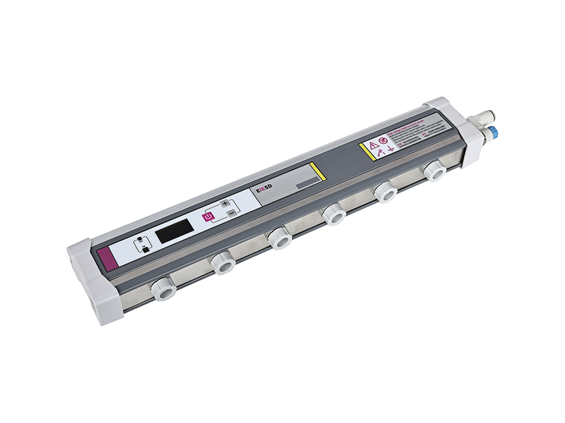
Executing an accurate offset voltage measurement requires strict adherence to procedural steps. Deviating from these steps introduces environmental variables that corrupt the final reading. You must control the test environment to get actionable data.
The setup phase dictates the validity of the entire test. The most important rule is positioning. Place the CPM's isolated conductive plate at the exact location of the static-sensitive process. This is the actual work surface where components reside. If you are assembling PCBs on a benchtop, place the plate flat on the benchtop.
Never place the testing plate directly in front of the blower or emitter points. Testing too close to the source provides artificially perfect readings that do not reflect the reality of the electrostatic field at the product level. Ensure the testing area is free from unnecessary insulators. Remove plastic documentation sleeves, ungrounded hand tools, and standard adhesive tapes from the immediate vicinity. These items project their own electric fields and will distort the local reading.
Once the equipment is properly positioned, initiate the measurement sequence. Follow these procedural steps carefully to ensure repeatable results across different technicians and shifts.
Turn on the ionizer and allow it to run for at least five minutes. This establishes a stable airflow and allows the ionization cloud to reach equilibrium in the workspace.
Power on the CPM or handheld field meter. If utilizing handheld verification tools, ensure the device is switched to the specific I.B (Ion Balance) mode. Standard field voltage mode will not yield correct results.
Ground the isolated conductive plate to zero out any residual charge. Most CPMs have a dedicated zeroing button that shorts the plate to ground internally.
Remove the ground connection from the plate. Allow the plate to float and interact with the ionized air.
Observe the voltage accumulation on the meter's display over a set period. Watch the fluctuations for 30 to 60 seconds.
Record the peak voltage readings. Note both the maximum positive and maximum negative voltage swings during the observation window.
Evaluating the recorded data requires comparing the offset voltage against industry-standard benchmarks. Acceptable tolerances depend heavily on the sensitivity of the components handled in that specific zone. You must align your pass/fail criteria with your facility's specific ESD control plan.
Manufacturing Environment | Component Sensitivity | Acceptable Offset Voltage Tolerance |
|---|---|---|
General Electronics Assembly | Standard ICs, robust passive components | < ±50V |
Advanced Semiconductor Packaging | Highly sensitive microprocessors, bare die handling | < ±35V |
Class 0 ESD Environments | MR heads, ultra-sensitive RF components, reticles | < ±10V to ±20V |
Any reading exceeding the established threshold demands immediate maintenance or replacement of the ionization unit. Do not allow production to continue under an unbalanced ionizer. The cost of a few minutes of downtime to clean emitter pins is negligible compared to the cost of scrapping a batch of high-value assemblies.
While balance ensures the ionizer does not cause harm, decay time proves that the ionizer actually performs its intended function. Measuring neutralization efficiency requires charging the test plate and timing the dissipation. This proves the ions are reaching the target with enough density to do the work.
The standard procedure requires measuring the decay time for both positive and negative charges independently. Begin by using the CPM's internal power supply to charge the isolated plate to +1000V. Once the charge stabilizes on the display, trigger the timer. Measure the exact time it takes for the voltage to decay to +100V. Record this value.
Next, reverse the polarity. Charge the plate to -1000V and measure the time required to decay to -100V. Both times must fall within the acceptable limits defined by your facility's ESD control plan. Significant discrepancies between positive and negative decay times indicate severe emitter pin degradation on one specific polarity. For example, if the positive decay is 2 seconds but the negative decay is 8 seconds, the negative emitter pins are likely heavily contaminated with silicon dioxide.
Neutralization efficiency does not exist in a vacuum. It is heavily dependent on physical distance and environmental airflow. Optimal decay times generally occur between 6 inches and 42 inches from the ionization unit. Beyond 42 inches, the concentration of ions drops off significantly. This leads to exponentially longer decay times that may fail to meet process requirements.
Understand how facility infrastructure impacts the Ion delivery path. Laminar airflow in cleanrooms can push ions away from the target surface if the ionizer is improperly angled. HVAC cross-drafts can scatter the ionization cloud before it reaches the benchtop. Physical obstructions like shelving, large test equipment, or even stacked product bins block ions from reaching the work surface entirely. Always test with the bench configured exactly as it is during active production.
Even with calibrated equipment, procedural errors can render test data useless. Technicians must understand common failure points to ensure accurate verification. Bad data is worse than no data because it breeds false confidence.
Testing directly at the emitter points remains the most common failure point in ionization verification. The physics of air ionization involve rapid recombination. Positive and negative ions naturally attract each other. They recombine into neutral air molecules shortly after leaving the emitter pins.
Testing too close to the ionizer ignores this recombination effect. It results in falsely optimistic data. You might measure a perfect balance and a lightning-fast decay time one inch from the blower, but the actual work surface three feet away receives zero ionization. The only metric that matters is the volume of ions that successfully survive the journey to the actual work surface to neutralize the product.
Improper grounding of the testing equipment skews results dramatically. If the CPM chassis is not securely connected to a known facility ground, the reference voltage floats. This renders the measurements entirely inaccurate. Always verify the ground connection of your test equipment before initiating a sequence.
Furthermore, the presence of highly charged insulators near the test zone creates environmental interference. A standard plastic trash can, a roll of Kapton tape, or a plastic chemical squeeze bottle positioned too close to the CPM plate will project its own electric field. This field overpowers the ions and causes the meter to register a false offset voltage. Clear the test area of all non-essential insulators.
The technician conducting the test introduces a significant variable. The human body acts as a capacitor, capable of storing and projecting static charge. If an ungrounded technician leans over the CPM during a test, their body capacitance interferes with the readings. The meter will measure the charge on the technician's clothing rather than the balance of the ionizer.
Mitigate this risk by enforcing strict personnel grounding protocols during testing. Technicians must wear properly tested, grounded wrist straps and static-dissipative smocks. They should also maintain a distance of at least 12 to 18 inches from the isolated plate while the measurement is actively recording. Stand back, let the meter stabilize, and record the true environmental reading.
Testing is only the diagnostic phase. The data you collect must drive an effective maintenance strategy. Different maintenance cadences carry distinct operational costs and risk profiles. You must align your strategy with your production realities.
Determine the appropriate maintenance schedule by evaluating the cost of testing labor against the financial risk of yield loss. High-volume semiconductor lines cannot afford a single shift of unbalanced ionization. A failure here justifies daily testing or automated monitoring. Lower-risk assembly areas handling robust components might operate safely with quarterly verification.
Compare the operational costs of manual, schedule-based testing against the capital expenditure required to upgrade to advanced monitoring systems. Paying a technician to walk the floor with a CPM every morning adds up to hundreds of labor hours annually. Upgrading your infrastructure might present a higher upfront cost but delivers long-term stability.
Many modern facilities are transitioning from manual, schedule-based testing to deploying ionizers with built-in, continuous balance monitoring and alarm systems. These smart units constantly measure their own offset voltage. They trigger visual or audible alarms if they drift out of specification. This eliminates the labor costs associated with manual daily checks and provides immediate notification of a failure.
However, if continuous monitoring is unavailable, highly critical environments often mandate an ion balance test at the start of each shift. Relying on monthly or quarterly checks in a Class 0 environment leaves the product exposed to unacceptable risk between verification cycles. If an ionizer fails the day after a quarterly check, you will process three months of defective product before discovering the issue.
Test failures directly dictate maintenance actions. Failing an offset voltage test or experiencing prolonged decay times is the primary indicator that emitter points require immediate attention. In most industrial environments, silicon dioxide accumulates on the tips of tungsten or titanium emitter pins. This appears as a white, crusty buildup.
This buildup insulates the pin. It suppresses corona discharge and skews the ion output. Implement specialized cleaning protocols using approved cleanroom swabs and 99% isopropyl alcohol to remove this contamination. Scrub the pins gently but firmly to remove the hardened deposits. When cleaning no longer restores acceptable decay times, the emitter pins have physically eroded. They lose their sharp point and become blunt. At this stage, they require complete replacement to restore the unit to factory specifications.
Audit your current ionization verification schedule immediately to ensure it aligns with actual production risks and industry standards.
Procure calibrated Charged Plate Monitors for your quality assurance team to replace reliance on uncalibrated or handheld spot-check tools for formal audits.
Establish a strict, documented protocol for emitter pin cleaning using approved solvents and swabs based on the failure data collected during routine testing.
Train all floor technicians on the physics of air ionization, emphasizing the critical importance of keeping the airflow path clear of physical obstructions.
A: Acceptable offset voltage depends entirely on your facility's specific ESD control program plan and the sensitivity of the components handled. General electronics manufacturing often accepts ±50V. However, highly critical environments handling Class 0 sensitive devices typically require offset voltages maintained tightly between ±10V and ±35V.
A: Testing frequency varies by requirement. Qualification testing occurs during initial installation or after major repairs. Periodic verification (ANSI/ESD TR53) is typically performed quarterly or bi-annually for compliance. However, critical manufacturing lines often require daily or shift-based spot checks to ensure continuous protection against static damage.
A: Ion balance (offset voltage) measures the ratio of positive to negative ions produced; an imbalance creates a dangerous static charge. Decay time measures the speed of static neutralization, specifically how long it takes to reduce a known charge (e.g., 1000V to 100V) across a specific distance.
A: A standard field meter alone cannot measure ion balance. It requires an attachable isolated conductive plate assembly to capture the ions. Furthermore, the meter must be specifically set to I.B (Ion Balance) mode to measure the offset voltage accurately rather than standard surface charge.
A: An ionizer can produce a perfectly balanced ratio of ions but fail to deliver enough volume to the target. Causes include low fan speed, excessive distance from the work surface, physical obstructions blocking airflow, or blunt, worn emitter pins that suppress overall ion generation.
A: ANSI/ESD STM3.1 is the industry-standard test method for evaluating the performance of air ionization systems used to neutralize static charges. It defines the precise laboratory-grade procedures and equipment requirements (like using a Charged Plate Monitor) necessary for the formal qualification of ionizers.
