
Views: 0 Author: Site Editor Publish Time: 2026-09-11 Origin: Site


Industrial static control systems do not operate at peak efficiency indefinitely. Ambient environmental factors inevitably degrade their output over time. As particulate matter accumulates on the equipment, the electrical corona discharge weakens. This leads to inadequate static neutralization across your production line. You then face increased risks of electrostatic discharge events, material jams, and product contamination. Unplanned downtime disrupts your entire operation. Implementing a rigorous, standardized approach to ionizing bar maintenance is essential for restoring baseline performance. Specifically targeting emitter needle contamination extends equipment lifespan and maintains process yields. We must address this degradation proactively. Relying on reactive troubleshooting guarantees production losses. A structured maintenance protocol eliminates these hidden inefficiencies and keeps your manufacturing floor running smoothly.
Performance Degradation is Inevitable: Dust, airborne oils, and silica naturally gravitate to high-voltage emitter needles, insulating the tips and severely reducing ion output.
Validation is Mandatory: Visual inspections are insufficient; maintenance efficacy must be verified using static field meters or charged plate monitors to ensure balance and decay times meet operational tolerances.
Methodology Matters: Utilizing incorrect cleaning solvents or abrasive tools can permanently damage tungsten or titanium emitter points, necessitating premature replacement.
Safety and EHS Clarity: It is vital to distinguish industrial static elimination from harmful ionizing radiation to ensure operator confidence and compliance.
Preventative Scheduling Reduces Costs: Transitioning from reactive troubleshooting to a scheduled maintenance framework minimizes production interruptions and stabilizes static control environments.
Table of Contents
High voltage applied to emitter pins provides immense electrical energy. This energy breaks electrons away from surrounding air molecules. The process creates necessary ion pairs for static neutralization. These ions flood the immediate atmosphere. They seek out opposite charges on moving webs or assembly parts. Neutralization happens instantly when ions contact charged surfaces. The continuous generation of these ions relies entirely on a sharp emitter point. The sharp geometry concentrates the electrical field. It allows the voltage to exceed the dielectric strength of the air. We must clarify the terminology surrounding this process. Industrial electrical corona discharge differs completely from high-energy radiation. Health organizations monitor X-rays and gamma rays. Those forms alter human cells. An Ionizing Bar simply splits air molecules electrically. It poses no radiation hazard. Addressing this distinction resolves common Environmental Health and Safety (EHS) misconceptions. Operators often fear equipment they do not understand. Education eliminates this fear and encourages proper upkeep.
Different power delivery methods affect how these ions generate. Alternating Current (AC) systems pulse positive and negative voltage to the same pin. Direct Current (DC) systems dedicate specific pins to positive or negative charges. Pulsed DC systems alternate these charges at programmable frequencies. Each method creates a distinct corona field. The physical sharpness of the tungsten or titanium needle dictates the efficiency of this field. A microscopic radius at the tip ensures maximum field concentration. When this geometry remains pristine, the power supply operates at minimal load. The system easily generates millions of ions per second. Maintaining this sharp geometry is the entire foundation of static control upkeep.
High-voltage fields act like magnets for airborne particulates. We call this the electrostatic precipitator effect. Emitter needles constantly attract microscopic debris from the environment. Carbon dust from machinery settles directly on the pins. Manufacturing aerosols coat the sharp metal tips. Humidity induces rapid oxidation on exposed surfaces. This buildup physically impacts the needle tip over time. It blunts the concentrated electrical field. A blunted field prevents efficient ion pair creation. The total volume of generated ions drops significantly. The insulating layer forces the power supply to work harder. It attempts to push voltage through the dirt crust. Eventually, the corona discharge collapses entirely.
Different industries face unique contamination challenges. Plastics manufacturing releases vaporized slip agents. These agents form a sticky, clear film on the emitters. Paper converting fills the air with cellulose fibers. These fibers bridge the gap between the pin and the ground casing. Electronics assembly generates sticky solder fumes. These fumes bake onto the hot emitter tips. Each contaminant requires specific removal strategies. Ignoring this buildup leads to a cascading failure. The power supply transformer overheats as it tries to overcome the resistance. The internal capacitors degrade prematurely. What starts as a simple dirty needle eventually destroys the entire hardware unit.

You must establish baseline performance metrics for your equipment. Optimal discharge times dictate how fast charges neutralize. We call this the decay rate. A healthy system reduces a 1000-volt charge to 100 volts in under one second. Offset voltage measures the overall ion balance. A properly functioning unit produces equal positive and negative ions, resulting in an offset near zero volts. Failing equipment presents clear operational symptoms. You will notice these issues immediately on the production floor.
Increased web breaks occur on high-speed converting lines.
Operators experience nuisance static shocks during material handling.
Defect rates climb rapidly in sensitive electronic assemblies.
Dust clings stubbornly to finished goods despite air blow-offs.
Sensors misread product positions due to static interference.
These signs indicate severe emitter contamination. Visual inspection fails to reveal microscopic degradation. You need empirical data to confirm failure. Waiting for these symptoms means you are already losing money. Proactive measurement prevents these production hurdles. We use specific metrics to define a pass or fail state for static control hardware.
Performance Metric | Factory Baseline (Clean) | Degraded State (Dirty) | Operational Impact |
|---|---|---|---|
Positive Decay Time (1000V to 100V) | 0.5 to 1.5 seconds | > 4.0 seconds | Slow neutralization, material jamming |
Negative Decay Time (-1000V to -100V) | 0.5 to 1.5 seconds | > 4.0 seconds | Incomplete static removal, dust attraction |
Offset Voltage (Ion Balance) | ± 10 Volts | > ± 50 Volts | Induces charge on neutral components, ESD damage |
Effective Coverage Area | 24 to 36 inches | < 12 inches | Dead zones across the production web |
Routine upkeep relies heavily on dry cleaning techniques. You should use specialized, non-abrasive static brushes. These brushes sweep away loose dust safely. They feature soft, conductive bristles designed for high-voltage equipment. Never use standard nylon brushes. They generate their own static charges during friction. Never use brass or steel wire brushes. Metal bristles scratch the precision-machined emitter points. Scratches create secondary emission points. This distorts the corona field permanently. Establish a strict frequency for dry brushing. Heavy industrial environments require daily intervention. Operators should perform this at the end of every shift. Cleanrooms require less frequent attention. Monthly brushing usually suffices in highly filtered environments.
Dry cleaning serves as your first line of defense. It prevents heavy particulate buildup. However, it has strict limitations. It cannot remove baked-on residues. It simply smears oily films across the housing. When brushing, use a single, continuous motion. Sweep parallel to the bar housing. Do not jab the bristles directly into the pins. Jabbing bends the emitters out of alignment. Misaligned pins arc directly to the ground channel. This triggers the power supply fault circuit. Train your operators to treat the emitters like precision instruments, not heavy machinery parts.
Deep restoration demands specific wet cleaning protocols. Select approved solvents carefully to avoid equipment damage. A mixture of 50% isopropyl alcohol (IPA) and 50% deionized water works best. This solution cuts through oils without leaving residue. Pure IPA evaporates too quickly. It leaves dissolved contaminants behind. The water slows evaporation effectively. Deionized water is absolutely essential. Tap water contains calcium and magnesium. These minerals remain on the pins after evaporation. They create dangerous conductive paths. These paths cause electrical arcing across the housing. Avoid standard industrial degreasers completely. They contain heavy surfactants. Surfactants leave thick insulative films on the emitters. Avoid silicone-based cleaners entirely. Silicone destroys ion emission instantly.
Use lint-free polyester cleanroom swabs. Cotton swabs leave microscopic fibers behind. These fibers catch fire in the high-voltage field. Scrub each pin gently until the metal shines. Pay close attention to the base of the pin. Contamination often pools where the pin meets the epoxy potting. If you leave dirt at the base, it eventually creeps back up the needle. Work systematically from one end of the housing to the other. Keep a dedicated waste bag for dirty swabs. Never reuse a swab on multiple pins. Cross-contamination defeats the entire purpose of the deep cleaning process.
Manual cleaning consumes massive amounts of maintenance labor. Automated systems offer a powerful alternative. Some units feature integrated, motorized brush cartridges. These mechanisms sweep the pins at programmed intervals. They travel the entire length of the housing automatically. You must assess the return on investment carefully. Automated systems require higher initial capital expenditure. However, they drastically reduce manual maintenance labor. They also ensure perfectly consistent ion output over time. Facilities struggling with labor shortages benefit greatly. The trade-off makes sense for hard-to-reach installations.
If a unit sits inside a complex web path, manual cleaning requires major machine disassembly. Automation keeps the line running without interruption. It prevents the silent degradation that plagues neglected manual systems. Consider the environmental factors before purchasing automated units. Highly viscous contaminants like adhesives or heavy greases will jam motorized brushes. Automated systems excel in dry, dusty environments like paper mills or textile plants. They struggle in wet or sticky environments. Match the technology to your specific production reality.
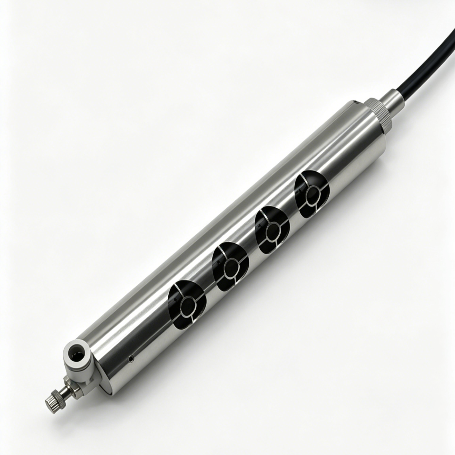
Strict adherence to Lockout/Tagout (LOTO) procedures is mandatory. You are working with high-voltage industrial equipment. Verify the power supply is completely de-energized before beginning. High voltage systems hold dangerous residual charges. Ground the housing to discharge any remaining capacitance. Do this before making physical contact with the pins. EHS communication remains vital during preparation. Ensure maintenance staff understand the equipment fully. They are working with electrical devices. They are not handling hazardous radiation sources. Clear communication prevents unnecessary panic. Follow these specific preparation steps strictly.
Disconnect the main power supply from the wall receptacle or control panel.
Apply a physical lock and tag to the power source to prevent accidental activation.
Wait two full minutes for internal capacitors to bleed down completely.
Touch a grounded probe to the emitter pins to clear any residual charge.
Verify zero voltage using a calibrated high-voltage meter.
Put on appropriate cleanroom gloves to prevent transferring skin oils to the pins.
Prepare your 50/50 IPA and deionized water solution in a clean, static-dissipative container.
Apply solvent carefully during the cleaning procedure. Never over-saturate the external housing. Liquid must not seep into internal circuitry. Dip the cleanroom swab into the IPA mixture. Tap off excess liquid against the container edge. Apply proper pressure to the needle tip. Clean the surface without bending the emitter. Misaligning the pin alters the electrical field geometry. Snapping the emitter ruins the module entirely. Rotate the swab gently around the point. Discard dirty swabs immediately. Do not dip a dirty swab back into the clean solvent. This contaminates your entire cleaning supply.
Focus on the physical technique. Hold the swab at a 45-degree angle to the pin. Twirl the swab between your thumb and forefinger. This motion lifts the dirt off the metal. Scrubbing back and forth simply pushes the dirt around. Inspect each pin with a bright flashlight after swabbing. The metal should reflect light evenly. If you see dull spots, repeat the process with a fresh swab. Allow required drying times before re-energizing the system. Residual alcohol causes severe electrical arcing. It can trigger catastrophic short circuits. Wait at least fifteen minutes after cleaning. Ensure all visible moisture has evaporated completely. Use clean, compressed air to accelerate drying if necessary, but ensure the air line has an oil and water trap installed.
Cleaning means nothing without empirical validation. Use a Charged Plate Monitor (CPM) for accurate testing. Measure both positive and negative decay times. Compare these figures against factory baselines. Document the restored ion balance meticulously. An unbalanced unit generates a dangerous offset voltage. This stray voltage damages sensitive electronic components. It also attracts dust to painted surfaces. Proper validation proves the maintenance cycle succeeded. It provides a documented history of equipment health.
Position the CPM exactly at the working distance of the application. If the bar normally sits 12 inches above the web, place the CPM plate 12 inches away. Do not test the unit right against the pins. That provides false readings. Record the temperature and humidity during the test. Environmental factors heavily influence decay rates. If decay times remain high after cleaning, you have a deeper problem. The power supply might be failing. The needles might be irreversibly worn. Validation separates simple contamination from permanent hardware failure. Log these results in your maintenance database for future reference.
Sometimes cleaning cannot restore baseline performance. You must identify irreversible emitter wear accurately. Constant high voltage alters the metallurgy of the pins over time. Look for visual and tactile indicators of permanent damage. Deep pitting on the needle surface catches a swab during cleaning. Severe green or white oxidation resists IPA solvent completely. Physically blunted tips look flat under a magnifying glass. When you observe these conditions, cleaning becomes a waste of labor.
The physics of blunted needles explains the system failure. Sharp points concentrate the electrical field perfectly. Flat tips disperse the energy widely. The system requires much higher voltages to achieve the same discharge. This leads to severe system strain. The power supply overheats. The transformer degrades rapidly. Cleaning a blunted needle wastes valuable maintenance time. You cannot restore a sharp point with chemical solvents. Attempting to file or sand the pins manually destroys the factory calibration. Once the geometry is gone, the pin is dead.
Evaluate your equipment design carefully before committing to deep cleaning. Some systems feature replaceable emitter pin cartridges. Others use fixed-pin designs embedded in epoxy. Replaceable modules offer excellent scalability. You simply swap the cartridge when needles degrade. Fixed-pin designs require full unit replacement. Conduct a thorough cost-benefit analysis. Calculate the labor cost of deep cleaning heavily degraded bars. Compare this against the material cost of swapping emitter modules.
Often, swapping cartridges saves valuable production time. It guarantees immediate return to factory specifications. You can clean the dirty cartridges offline while the machine runs. Fixed-pin units demand more rigorous preventative care. Once they degrade past the point of cleaning, the entire capital asset is lost. Factor this into your future equipment purchasing decisions. Modular designs cost more upfront but save thousands in maintenance labor over a five-year lifespan. Standardize your facility on easily serviceable hardware to streamline your entire static control program.
Create a rigid framework for determining maintenance intervals. Base these intervals on strict environmental audits. Dusty environments require weekly interventions. Cleanrooms might only need quarterly checks. Integrate these tasks into existing operational frameworks. Total Productive Maintenance (TPM) schedules work perfectly for this. Tie maintenance alerts directly to your SCADA systems. Scheduled interventions prevent sudden equipment failures. Document every cleaning cycle in your computerized maintenance management system (CMMS).
Track the decay rates over time. This data reveals the true degradation curve of your environment. It allows you to optimize the cleaning frequency. You stop over-maintaining clean units. You stop neglecting dirty units. Data-driven scheduling maximizes your maintenance labor efficiency. Assign specific zones to specific technicians. Accountability ensures the work gets done correctly. Review the CMMS data quarterly. Adjust the frequencies based on seasonal changes. Winter months bring low humidity, which increases static generation and requires tighter maintenance tolerances.
Implementation carries specific operational risks. Operator injury remains a primary concern during high-voltage work. Improper training leads directly to equipment damage. Mitigate this by developing standardized operating procedures (SOPs). Conduct hands-on training for all maintenance technicians. Watch them perform the swabbing technique. Correct aggressive scrubbing immediately. Ensure they understand the difference between AC and DC systems, as cleaning techniques sometimes vary between manufacturers.
Unnoticed performance drops present another massive risk. Systems degrade silently between scheduled maintenance cycles. Mitigate this by installing inline sensor technology. These sensors provide continuous monitoring of static levels on the web. They trigger alarms before defect rates climb. They alert operators the moment ion balance shifts. Continuous monitoring bridges the gap between manual cleaning cycles. It guarantees process stability around the clock. Combine manual cleaning with automated monitoring for the most robust static control strategy possible.
Conduct a facility-wide audit of all installed static control devices to establish current operational baselines.
Measure current decay rates and offset voltages using a calibrated charged plate monitor.
Establish a formalized, data-driven cleaning schedule based on the environmental severity of each production zone.
Procure approved 50/50 IPA solvents and lint-free polyester swabs for the maintenance team.
A: Frequency depends entirely on the operating environment. Cleanrooms may require quarterly cleaning. Heavy industrial applications like paper converting or textiles may require weekly or even daily maintenance. Monitor decay rates to determine the exact schedule.
A: No. While they share the word "ionizing", industrial static eliminators use electrical corona discharge. They do not emit high-energy ionizing radiation like X-rays or gamma rays that alter human cells. They simply break electrons away from air molecules.
A: A solution of 50% isopropyl alcohol (IPA) and 50% deionized water is the industry standard. Avoid harsh chemicals, industrial degreasers, or tap water. These liquids leave conductive or insulative residues that destroy performance.
A: No. Wire brushes or abrasive tools will scratch, blunt, or break the precision-machined emitter points. This permanently degrades the ability to generate ions. Use only manufacturer-approved soft conductive brushes or lint-free cleanroom swabs.
A: Success must be quantified using a static field meter or Charged Plate Monitor (CPM). You must verify that the decay time and ion balance have returned to factory specifications. Visual inspection alone is never sufficient.
A: Needles should be replaced when they show signs of physical pitting, severe corrosion, or blunting. If decay times remain outside acceptable tolerances even after a thorough wet cleaning, the hardware is permanently worn.
A: Yes. Always disconnect the power supply and follow standard Lockout/Tagout (LOTO) procedures. Ground the housing to discharge residual capacitance. This prevents severe electrical shock and catastrophic equipment damage.
